
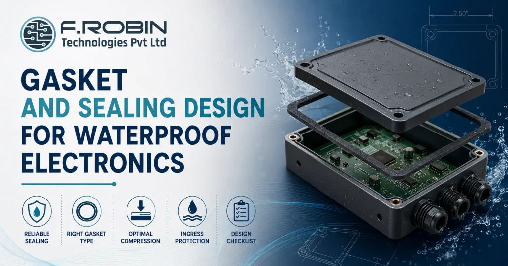
“How do I get a reliable seal?” is one of the most common questions in waterproof electronics design, and the honest answer is that reliability comes from a handful of deliberate decisions, not a single magic gasket material. Gasket and sealing design determines whether a product genuinely holds its IP rating in the field or fails quietly the first time it gets rained on.
This how-to guide walks through the practical decisions behind reliable gasket and sealing design — choosing the right gasket type, designing for proper compression, planning a continuous seal path, and matching your design to the IP rating your product actually needs. Whether you are sealing a simple outdoor sensor enclosure or a fully ruggedized industrial product, these fundamentals apply, and getting them right the first time avoids expensive field failures down the line.
Why Gasket and Sealing Design Is Harder Than It Looks
A gasket looks simple: a strip of material between two surfaces. In practice, gasket and sealing design fails in the field far more often than it fails in the lab, because real enclosures have corners, fasteners, cable entries, and manufacturing tolerance that a simple flat-surface test never exposes.
Reliable sealing requires treating the gasket as one part of a system — material, groove geometry, compression force, and the continuity of the seal path around the whole enclosure — rather than a component you simply drop in and hope works. Get any one part of that system wrong, and water finds the gap.
This system-level thinking is the same discipline behind good electronic enclosure design more broadly — sealing is one part of the enclosure, not a separate afterthought bolted on at the end.
Choosing the Right Gasket Type
Different gasket types suit different enclosure geometries and environments. Closed-cell foam gaskets compress easily and forgive minor surface irregularities, making them a common, cost-effective choice for enclosure lids and access panels. O-rings provide excellent, consistent sealing in a compact groove, well suited to cylindrical connectors and small access ports.
Silicone and rubber extrusion gaskets offer good chemical and temperature resistance for demanding environments, while liquid-dispensed gaskets — applied as a bead that cures in place — suit complex, non-uniform sealing paths where a pre-formed gasket would be difficult to fit precisely. Match the gasket type to your enclosure’s geometry and environmental demands, rather than defaulting to whatever was used on a previous, possibly quite different, product.
Your material choice here also interacts with the enclosure substrate itself — see our comparison of sheet metal vs die-cast vs plastic enclosures for how the base material affects gasket groove design and sealing surface quality.
Designing for Proper Compression
A gasket only seals effectively within its intended compression range — typically 20-30% of its original thickness for most closed-cell foam materials, though this varies by material and manufacturer. Too little compression leaves gaps the gasket cannot bridge; too much compression can cause permanent set, where the gasket loses its ability to spring back and seal on the next opening.
Gasket and sealing design must account for real manufacturing tolerance in the mating parts, not just nominal dimensions. If tolerance stack-up could push compression outside the gasket’s effective range at either extreme, the seal will fail intermittently — precisely the kind of failure that is hardest to catch in testing and most damaging once it reaches the field.
Planning a Continuous Seal Path
A seal is only as good as its weakest point, and that weakest point is almost always a corner, a fastener boss, or a cable entry where the gasket path changes direction or gets interrupted. Plan the seal path as a single, continuous loop around the entire enclosure opening, with generous, consistent radii at corners rather than sharp turns that a gasket cannot follow cleanly.
Cable and connector entries deserve particular attention in gasket and sealing design, since they punch through what would otherwise be a clean, continuous seal path. Use dedicated cable glands or grommets rated to your target IP level, and ensure the gasket groove routes cleanly around these penetrations rather than stopping and restarting at each one.
Matching Design to Your IP Rating Target
Ingress protection ratings define what your gasket and sealing design actually needs to achieve the first digit rates protection against solids (dust), the second against liquids (water). A common target like IP65 means dust-tight and protected against water jets, while IP67 adds protection against temporary immersion, demanding a more robust seal design and typically tighter compression tolerances.
Design to your real target, not the highest rating available. Over-specifying building an IP67 seal for a product that only needs IP54 indoor protection adds cost and assembly complexity for no operational benefit, while under-specifying risks field failures the moment the product meets real-world conditions.
Gaskets Also Handle EMI/EMC Shielding
Gasket and sealing design is not only about keeping water and dust out — the same gasket location often has to maintain electrical continuity across an enclosure seam to control EMI/EMC. These are two genuinely different jobs, and a gasket chosen only for environmental sealing does nothing for shielding unless it is also electrically conductive.
Standard closed-cell foam or silicone gaskets seal against moisture and dust but are electrical insulators, so they leave a gap in the shielding at every seam they cover. If your product has EMI/EMC requirements, you need a conductive gasket material — conductive elastomer, knitted wire mesh, or beryllium copper fingerstock — at the seam, or a combination gasket that provides environmental sealing and EMI continuity together.
Combination gaskets exist specifically for this dual requirement: a conductive core or conductive-coated foam that seals against the environment while also bridging the shielding across the seam. When both requirements apply to the same enclosure, specify the combination gasket explicitly in your gasket and sealing design rather than assuming a good environmental seal automatically delivers EMI performance — the two properties do not come from the same material property, and a gasket optimized for one alone can fail the other silently.
For the mechanical side of shielding continuity in more depth, see our guide to how EMI/EMC compliance starts in the enclosure, which covers shielding, bonding, and apertures alongside gasketing.
Common Failure Points
- Corners and direction changes in the seal path, where gasket geometry is hardest to control precisely.
- Cable and connector entries that interrupt the continuous seal path.
- Fastener bosses too far apart, allowing the enclosure to bow and reduce local compression between fasteners.
- Gasket material degradation from UV exposure or temperature extremes outside its rated range.
- Manufacturing tolerance stack-up pushing compression outside the gasket’s effective range.
Reviewing a design specifically against these known failure points catches most sealing problems before they reach a physical prototype.
A Real-World Example
Picture an outdoor sensor enclosure targeting IP65. The lid uses a closed-cell foam gasket compressed correctly at 25%, but the design places fasteners far apart at the corners only, leaving the long straight edges of the lid free to bow slightly under normal handling. That bowing locally reduces compression along the edges, and the product intermittently fails water testing not because the gasket material was wrong, but because gasket and sealing design treated fastener spacing as a separate mechanical decision rather than part of the sealing system.
Adding two additional fasteners along each long edge restores even compression around the full seal path, and the same gasket material now passes reliably. The fix cost almost nothing in materials, but it required recognizing that gasket and sealing design is a system-level problem fasteners, gasket, and enclosure stiffness all have to work together, not just the gasket in isolation.
A Sealing Design Checklist
- Confirm the target IP rating and design to it deliberately, not by default.
- Choose a gasket type matched to your enclosure geometry and environment.
- Verify compression stays within the gasket material’s effective range across real manufacturing tolerance.
- Plan a continuous seal path with generous corner radii.
- Use rated cable glands or grommets at every cable and connector entry.
- If EMI/EMC applies, specify a conductive or combination gasket, not just an environmental seal.
- Space fasteners closely enough to maintain even compression around the full seal path.
- Validate the design with real ingress testing before committing to tooling.
Working through this checklist before finalizing gasket and sealing design catches the failure modes that are otherwise invisible until a product meets real water or dust exposure.
This checklist works alongside the broader mechanical design services buyer’s guide, which covers the wider evaluation criteria for a mechanical design partner beyond sealing alone.
Common Mistakes to Avoid
- Choosing a gasket material without checking its compression range against your actual design tolerance.
- Routing the seal path with sharp corners the gasket cannot follow cleanly.
- Treating cable entries as an afterthought instead of part of the continuous seal path.
- Over- or under-specifying the IP rating relative to the product’s real operating environment.
- Skipping ingress testing on a real prototype before committing to production tooling.
Avoiding these keeps gasket and sealing design reliable in the field, not just on paper.
Key Takeaways
- Reliable gasket and sealing design comes from a system of decisions, not a single gasket material choice.
- Match gasket type — foam, O-ring, extrusion, or liquid-dispensed — to your enclosure geometry and environment.
- Design compression within the gasket’s effective range, accounting for real manufacturing tolerance.
- Plan a continuous seal path with generous corner radii and rated cable entries.
- Design to your real IP rating target, not the highest rating available by default.
- If EMI/EMC shielding matters, specify a conductive or combination gasket — standard foam or silicone gaskets do not shield.
- Validate with real ingress testing before committing to production tooling.
