
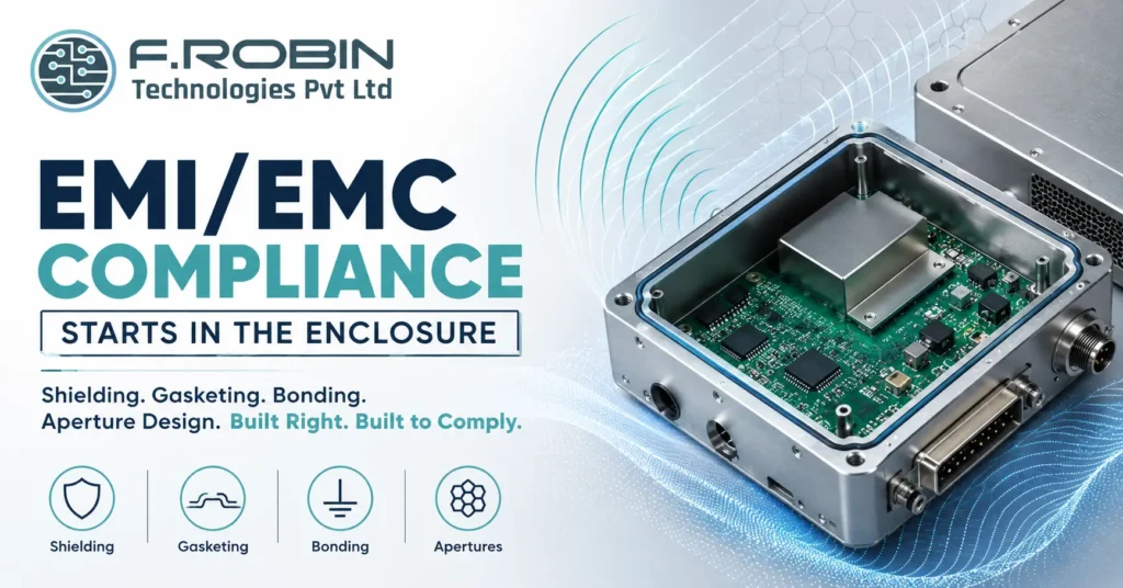
EMI/EMC compliance is too often treated as a test-lab problem something to fix after the board is built and the enclosure is finished. In reality, EMI/EMC compliance starts in the enclosure, long before any product reaches a test chamber. Shielding, gasketing, bonding, and aperture design decide whether your product passes or fails, and retrofitting them after the fact is slow, expensive, and often only partly effective.
This guide explains how enclosure design drives EMI/EMC compliance. We cover the mechanical fundamentals shielding, gasketing, bonding, and apertures the standards you need to know, and the best practices that turn compliance from a last-minute scramble into a built-in feature of ruggedized, standards-compliant design.
Why EMI/EMC Compliance Starts in the Enclosure
Electromagnetic interference does not respect the boundary between board and box. Signals radiate from the PCB, and the enclosure either contains them or lets them escape. That is why EMI/EMC compliance starts in the enclosure: it is the last physical barrier between your electronics and the outside world, and its design decides how much energy gets through.
Fixing EMI/EMC problems after a failed test is far harder than designing them out. Adding shielding or gaskets to a finished enclosure often means costly tooling changes, and some fixes simply do not work once the mechanical design is frozen. Building compliance in from the start — through shielding, gasketing, bonding, and careful apertures — is dramatically cheaper and more reliable than debugging it afterward.
This is also why EMI/EMC compliance belongs firmly within mechanical enclosure design, not as an afterthought bolted on once the shape is set.
Shielding
Shielding blocks electromagnetic energy from entering or leaving the enclosure. It is the primary defence in EMI/EMC compliance and the first thing to plan for.
Common shielding approaches include:
- Conductive enclosure material, such as die-cast metal or metallized plastic.
- Internal shielding cans over sensitive or noisy components on the PCB.
- Continuous conductive paths, since a shield is only as good as its weakest gap.
- Coating non-conductive housings with conductive paint or plating when metal is not practical.
The goal is a continuous conductive boundary with no significant gaps. Every seam, vent, or opening is a potential leak, so shielding effectiveness depends as much on the details seams, joints, and closures as on the base material itself.
Gasketing
Where two enclosure panels meet, a plain metal-to-metal joint rarely provides consistent contact across its length. Gasketing closes those gaps with a conductive material that maintains electrical continuity along the seam.
Common EMI gasket types include:
- Conductive elastomer gaskets, compressible and effective for most seams.
- Beryllium copper fingerstock, durable and highly conductive for repeated openings.
- Conductive fabric-over-foam gaskets, good for larger or irregular gaps.
- Wire mesh gaskets, for high-shielding-effectiveness applications.
Choosing the right gasket depends on the frequency range, the compression available, environmental sealing needs, and how often the joint will be opened. Gasketing works hand in hand with bonding a gasket without a solid, low-impedance path to ground is far less effective.
Bonding and Grounding
Bonding creates a low-impedance electrical connection between enclosure parts, ensuring stray currents have a clear path rather than radiating as interference. Poor bonding is one of the most common causes of EMI/EMC compliance failures, because even a well-shielded enclosure leaks if its panels are not properly bonded together.
Good bonding practice includes:
- Direct metal-to-metal contact at joints, free of paint or anodizing that insulates the surface.
- Star or single-point grounding to avoid ground loops.
- Multiple bonding points around large panels, not just the corners.
- Low-impedance connections to chassis ground for cables and connectors.
Because bonding is easy to overlook in a purely mechanical review, it deserves explicit attention during design not just at final assembly. A gap in the bonding path can undo an otherwise well-shielded enclosure.
Apertures and Openings
Every enclosure needs openings for connectors, displays, vents, and buttons and each one is a potential leak in your EMI/EMC compliance. The size and shape of an aperture, relative to the wavelength of the interference, determines how much energy escapes.
Key aperture design principles:
- Keep openings small relative to the wavelength of concern; smaller apertures leak less.
- Use honeycomb vents for airflow that need shielding, since the cell geometry blocks radiation while allowing air through.
- Group small holes together rather than one large opening, since many small apertures leak less than one big one of the same total area.
- Shield cable entries with grounded connectors or ferrites where cables must pass through the boundary.
Apertures are often the last thing considered and the first thing that causes a compliance failure. Planning them early as part of PCB mechanical integration — avoids surprises late in the project.
Standards You Need to Know
EMI/EMC compliance is governed by recognized standards, and knowing which apply to your product early shapes your enclosure decisions. Common standards include:
- CISPR 32 / EN 55032 — emissions for multimedia equipment.
- IEC 61000-4 series — immunity to various disturbances.
- FCC Part 15 — emissions limits for electronic devices in the US.
- MIL-STD-461 — EMI requirements for military and defence equipment.
Identifying the relevant standard early lets you design the enclosure to the right margin from day one, rather than guessing and hoping. For ruggedized, standards-compliant design, this step is not optional — it defines the whole shielding and gasketing strategy.
A Compliance-by-Design Checklist
Use this checklist during enclosure design to build in EMI/EMC compliance from the start:
- ✅ Identify the applicable EMC standard and target margin early.
- ✅ Choose a conductive or coated enclosure material.
- ✅ Plan continuous shielding with no significant gaps at seams.
- ✅ Specify the right gasket type for each seam and frequency range.
- ✅ Design bonding points across every panel joint, not just corners.
- ✅ Keep apertures small, grouped, or filtered with honeycomb vents.
- ✅ Shield or filter every cable entry point.
- ✅ Plan for pre-compliance testing before the final design freeze.
Ticking every box before tooling dramatically improves your odds of passing formal testing the first time.
Common Mistakes to Avoid
Even experienced teams get caught out. Watch for these:
- Treating EMC as a test-lab problem, addressed only after a failure.
- Painting or anodizing bonding surfaces, insulating joints that need contact.
- Oversized or ungrouped apertures, leaking far more than expected.
- Skipping gaskets on seams to save cost, then failing certification.
- Ignoring cable entry points, a common and overlooked leak path.
- Designing the enclosure before knowing the applicable standard.
Avoiding these keeps your EMI/EMC compliance predictable instead of a last-minute scramble.
Key Takeaways
- EMI/EMC compliance starts in the enclosure, not the test lab — fixing it late is expensive.
- Shielding provides a continuous conductive boundary around sensitive electronics.
- Gasketing maintains electrical continuity across seams and panel joints.
- Bonding creates the low-impedance ground path that makes shielding effective.
- Apertures must be small, grouped, or filtered to avoid leaking interference.
- Identify your target standard early and design to it from the start.
Conclusion
EMI/EMC compliance starts in the enclosure, not the test lab. Shielding, gasketing, bonding, and thoughtfully designed apertures determine whether a product passes on the first try or bounces back from certification. Identify your target standard early, build compliance into the mechanical design from day one, and you turn a stressful last-minute scramble into a predictable, built-in outcome.
Frequently Asked Questions
The enclosure is the last physical barrier between your electronics and the outside world. Its shielding, gasketing, bonding, and aperture design determine how much electromagnetic energy escapes or enters, making mechanical design a critical part of EMI/EMC compliance long before laboratory testing begins.
Shielding creates a continuous conductive barrier using enclosure materials, conductive coatings, or internal shields to prevent electromagnetic energy from entering or leaving the product.
Conductive gaskets seal enclosure joints and seams while maintaining electrical continuity. This minimizes EMI leakage through gaps where simple metal-to-metal contact may not provide reliable conductivity.
Bonding provides a low-impedance electrical connection between enclosure panels, connectors, and grounding points, allowing unwanted currents to flow safely to ground instead of radiating as electromagnetic interference.
Every opening for connectors, ventilation, displays, or cables can become a source of electromagnetic leakage. Keeping apertures small, properly positioned, grouped, or filtered helps reduce emissions and improves EMC performance.
