
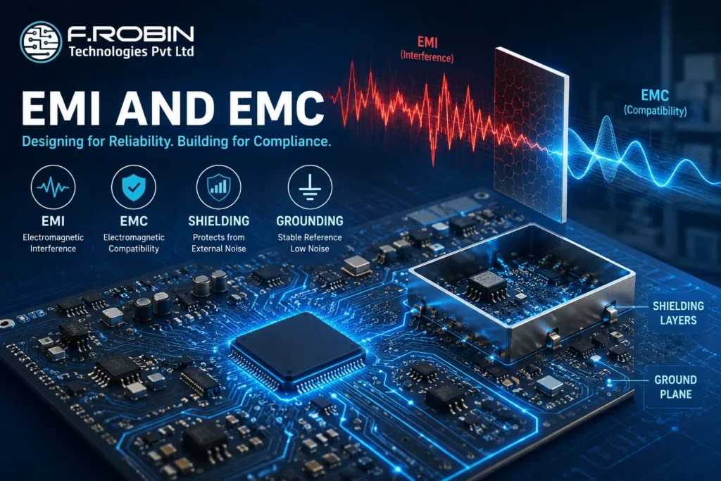
EMI and EMC are critical concepts in modern electronics, PCB engineering, and embedded system design. Electronic devices today operate in highly connected and signal-dense environments. From smartphones and industrial automation systems to automotive ECUs and medical electronics, every electronic product must function reliably without creating or receiving unwanted electromagnetic disturbances.
This is where EMI and EMC become essential in electronics and PCB engineering.
Electromagnetic interference (EMI) can disrupt signals, reduce device performance, and even cause system failures. Electromagnetic compatibility (EMC), on the other hand, ensures that electronic systems operate correctly without interfering with nearby devices.
Understanding EMI and EMC is essential for PCB designers, embedded engineers, electronics manufacturers, and product development teams aiming to build reliable and standards-compliant products.
In this guide, we will explain:
- What EMI and EMC mean
- The difference between EMI and EMC
- EMI and EMC testing methods
- EMI in PCB design
- EMC compliance requirements
- Best practices to reduce electromagnetic interference
What Is EMI?
Electromagnetic Interference (EMI) refers to unwanted electromagnetic noise or signals that disrupt the normal operation of electronic devices.
EMI can originate from:
- Switching power supplies
- High-speed PCB traces
- RF transmitters
- Motors
- Wireless devices
- Poor grounding systems
EMI affects signal integrity and may lead to:
- Data corruption
- Communication failure
- Reduced device reliability
- Product malfunction
Common Examples of EMI
- Noise in audio systems
- Wi-Fi signal disruption
- Display flickering
- Automotive sensor interference
What Is EMC?
Electromagnetic Compatibility (EMC) is the ability of an electronic device to operate correctly in its electromagnetic environment without causing or experiencing interference.
An EMC-compliant product:
- Emits acceptable electromagnetic noise
- Resists external electromagnetic disturbances
- Meets regulatory standards
EMC is critical for:
- Medical electronics
- Aerospace systems
- Automotive electronics
- Industrial control systems
- Consumer electronics
Difference Between EMI and EMC
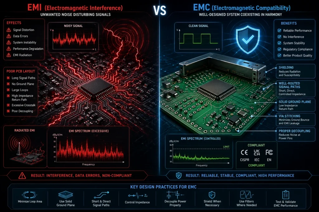
EMI vs EMC Comparison Table
| Parameter | EMI | EMC |
|---|---|---|
| Full Form | Electromagnetic Interference | Electromagnetic Compatibility |
| Meaning | Unwanted electromagnetic noise | Ability to function without interference |
| Focus | Problem source | System immunity and compliance |
| Impact | Causes signal disruption | Prevents malfunction |
| Goal | Reduce interference | Ensure reliable operation |
| Common Solution | Shielding and filtering | Compliance-focused PCB design |
Simple Explanation
EMI is the interference itself, while EMC is the ability of a system to handle or avoid that interference.
Types of EMI in Electronics
1. Conducted EMI
Conducted EMI travels through electrical conductors such as:
- Power lines
- Signal cables
- PCB copper traces
Sources
- Switching regulators
- Power converters
- Motor drivers
2. Radiated EMI
Radiated EMI spreads through electromagnetic waves in the air.
Sources
- Wireless transmitters
- RF modules
- High-frequency clocks
- Antennas
Why EMI and EMC Matter in PCB Design
EMI in PCB Design
Poor PCB layout is one of the leading causes of electromagnetic interference.
Common PCB EMI Problems
- Long signal traces
- Improper grounding
- High loop areas
- Crosstalk
- Poor decoupling capacitor placement
PCB Design Areas That Affect EMC
- Layer stack-up
- Return current paths
- Trace impedance
- Ground planes
- Signal routing
High-speed PCB designs require strong EMC considerations to avoid compliance failures.
Best PCB Design Practices for EMC
1. Use Proper Ground Planes
Continuous ground planes reduce return path impedance and lower EMI emissions.
2. Minimize Loop Areas
Smaller current loops reduce electromagnetic radiation.
3. Separate Analog and Digital Signals
This prevents noise coupling between sensitive circuits.
4. Add Decoupling Capacitors
Decoupling capacitors stabilize power integrity and reduce switching noise.
5. Optimize Layer Stack-Up
A proper multilayer PCB structure improves EMC performance significantly.
For advanced PCB layout optimization, explore the professional PCB design solutions offered by Frobintech PCB Layout Design Services .
EMI and EMC Testing Explained
What Is EMI and EMC Testing?
EMI and EMC testing verifies whether an electronic product:
- Emits acceptable electromagnetic noise
- Can withstand external interference
- Meets international compliance standards
Main EMC Tests
| Test Type | Purpose |
|---|---|
| Radiated Emissions | Measures electromagnetic radiation |
| Conducted Emissions | Measures noise through conductors |
| ESD Testing | Evaluates electrostatic discharge immunity |
| Surge Testing | Checks power surge resistance |
| RF Immunity Testing | Measures resistance to RF interference |
Why EMC Testing Is Important
EMC testing helps manufacturers prevent product failures, meet certification requirements, improve product reliability, reduce field issues, and achieve faster market approval.
EMC Compliance and Industry Standards
Products must satisfy regulatory electromagnetic standards before entering the market. Proper EMC compliance helps ensure reliable device operation, reduces interference risks, and supports global certification requirements.
Important EMC Standards
- FCC standards
- CE EMC directives
- CISPR standards
- IEC standards
- ISO automotive EMC standards
Products failing EMC compliance may:
- Fail certification
- Experience recalls
- Face legal restrictions
- Cause interference in critical systems
EMI Shielding Techniques
EMI shielding reduces electromagnetic noise using conductive or magnetic materials.
Common EMI Shielding Methods
Metal Shielding
Uses aluminum or copper enclosures to block electromagnetic waves.
Shielded Cables
Protect signal integrity in noisy environments.
Ferrite Beads
Suppress high-frequency noise in circuits.
Ground Shielding
Improves electromagnetic containment in PCB layouts.
EMI Filters
Reduce conducted interference in power lines.
Best Practices to Reduce EMI and Improve EMC
Practical EMC Design Guidelines
Use Shorter Signal Traces
Shorter traces reduce antenna effects and radiation.
Maintain Proper Grounding
Good grounding lowers noise coupling.
Avoid Sharp Trace Angles
Use 45-degree bends to improve signal flow.
Use Differential Pair Routing
Improves noise immunity in high-speed circuits.
Apply EMI Shielding
Shield sensitive areas from RF interference.
Perform Pre-Compliance Testing
Early testing helps identify EMC problems before production.
Key Takeaways
- EMI refers to unwanted electromagnetic interference.
- EMC ensures electronic devices operate reliably without interference.
- PCB layout plays a major role in EMI performance.
- EMC testing is essential for product certification.
- Proper grounding, shielding, and filtering reduce EMI issues.
- EMC compliance is critical for electronics manufacturing and global market approval.
Conclusion
As electronic systems become faster and more compact, understanding EMI and EMC is increasingly important for engineers and manufacturers.
From PCB design and embedded systems to industrial automation and consumer electronics, electromagnetic compatibility directly affects product reliability, compliance, and performance.
By implementing proper grounding, shielding, filtering, and PCB layout techniques, companies can reduce electromagnetic interference and improve EMC compliance effectively.
Organizations developing advanced electronic products should prioritize EMI and EMC considerations early in the design cycle to avoid costly redesigns and certification failures.
Need Expert PCB Layout Support?
Need expert support for EMC-friendly PCB layouts and high-speed electronics design?
Explore professional PCB design solutions from Frobintech PCB Layout Design Services
For project discussions and engineering consultation, contact the team here:
Contact FrobintechFAQ
The two main types of EMI are Conducted EMI and Radiated EMI. Conducted EMI travels through electrical conductors such as cables, power lines, and PCB traces, while Radiated EMI spreads through electromagnetic waves in the air and can affect nearby electronic devices and communication systems.
No. EMI refers to electromagnetic interference, while EMC refers to a device’s ability to operate without causing or receiving interference.
EMC is used to ensure that electronic devices function correctly without interfering with other nearby electronic systems.
You can reduce EMI and improve EMC by implementing proper grounding techniques, adding EMI shielding, optimizing PCB layout design, using EMI filters, and performing EMC testing during product development. These practices help minimize electromagnetic interference, improve signal integrity, and ensure reliable operation of electronic devices.
