
Electronics enclosure design in India is one of the most underestimated stages of hardware product development. Most engineering teams spend weeks optimising their PCB layout, then allocate a few days to the enclosure only to discover during production that the housing cracks under stress, traps heat around critical components, or fails its IP rating test because a cable gland was placed incorrectly.
The enclosure is not packaging. It is an engineering system in its own right one that must manage heat, withstand mechanical stress, meet environmental protection ratings, comply with regulatory standards, accommodate manufacturing tolerances, and still look and feel like a finished product. Getting it wrong costs time, tooling money, and in some applications, product safety.
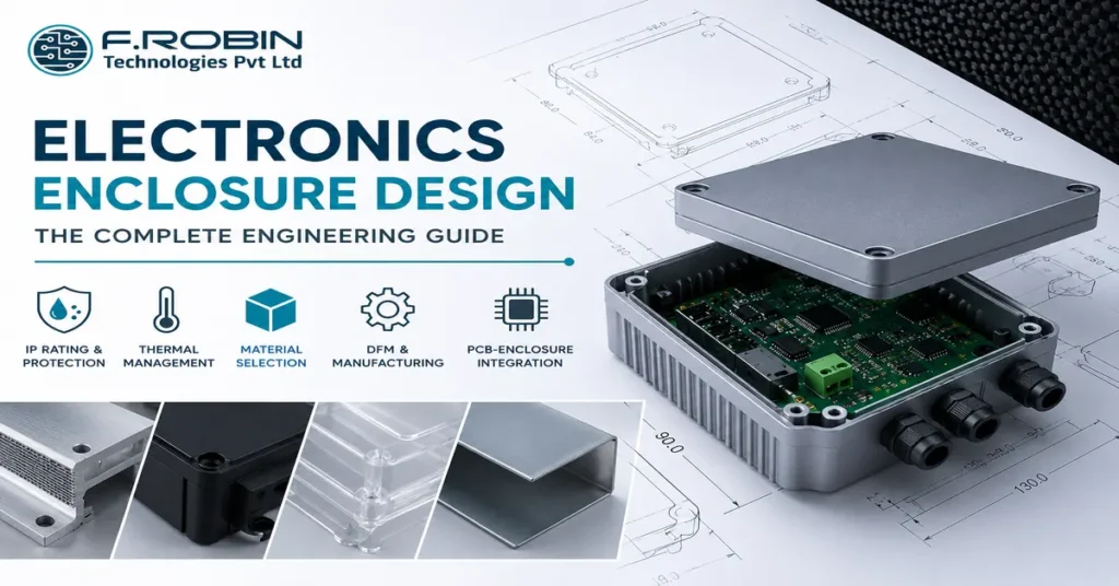
This guide covers everything you need to know about electronics enclosure design material selection, IP ratings, thermal management, DFM rules, and how the enclosure and PCB design must work together from the earliest stages of development.
1. What Is Electronics Enclosure Design?
Electronics enclosure design is the mechanical engineering discipline of designing the housing that protects and contains a printed circuit board and its associated components connectors, displays, switches, antennas, batteries, and wiring harnesses in a finished, deployable product.
A well-designed enclosure serves several simultaneous functions. First, it provides mechanical protection shielding the PCB from physical impact, vibration, and handling damage. Additionally, it provides environmental protection sealing against dust, moisture, humidity, and chemical exposure. Furthermore, it manages thermal performance providing pathways for heat generated by components to dissipate safely. Finally, it ensures regulatory compliance meeting EMI/EMC shielding requirements, UL flammability ratings, and CE marking requirements for the target market.
Why enclosure design must start alongside PCB layout
The most expensive mistake in product development is treating enclosure design as an afterthought. Consequently, when the enclosure design begins after the PCB is finalised, the mechanical engineer is forced to design around a fixed board rather than co-designing the two together. This leads to:
- Connectors positioned where the enclosure cannot accommodate them without complex cutouts
- Components too tall for the available internal clearance
- PCB mounting holes in locations that compromise structural integrity
- Thermal management solutions that require board respins to implement
At F.Robin Technologies, PCB layout and mechanical enclosure design are integrated processes. Our engineering team co-designs the board and its housing simultaneously, which reduces respins and significantly shortens time to production. Learn more about our PCB design and layout services at frobintech.com/pcb-layout-design.
2. Enclosure Material Selection
The choice of enclosure material is one of the most consequential decisions in the mechanical design process. Each material has specific trade-offs in mechanical strength, weight, thermal performance, cost, and manufacturability.
Choosing the Right Material
Aluminium (die-cast or machined) Aluminium is the preferred enclosure material for industrial, automotive, and outdoor electronics where thermal management, EMI shielding, and mechanical robustness are primary requirements. Die-cast aluminium is cost-effective at medium to high volumes, provides excellent heat dissipation (thermal conductivity 160–205 W/m·K), and offers natural EMI attenuation.
Machined aluminium is used for low-volume, high-precision enclosures instrument housings, test equipment, and aerospace electronics where dimensional accuracy and surface finish are critical. However, machined aluminium is significantly more expensive per unit than die-cast at volume.
ABS plastic (injection moulded) ABS (Acrylonitrile Butadiene Styrene) is the most common plastic enclosure material for consumer electronics, IoT devices, and indoor industrial products. It is lightweight, cost-effective at high volumes, easily coloured and textured, and straightforward to injection-mould with good dimensional consistency.
ABS is not suitable for outdoor applications without UV-stabilised additives or protective coatings, and it provides minimal inherent EMI shielding (unlike metal). For applications requiring EMI shielding in a plastic enclosure, internal conductive coatings or gaskets are required.
Polycarbonate (PC) Polycarbonate offers higher impact resistance than ABS, better optical clarity (relevant where display windows or light pipes are required), and superior heat resistance. It is commonly used in enclosures for outdoor lighting, medical devices, and safety equipment. PC is more expensive than ABS and can be more challenging to mould without warping in thick sections.
PC/ABS blends PC/ABS blends combine the impact resistance of polycarbonate with the processability and lower cost of ABS. They are widely used in handheld devices, ruggedised consumer electronics, and industrial handhelds where both aesthetics and durability matter.
Sheet metal (steel or aluminium) Sheet metal enclosures bent and welded from steel or aluminium sheet are cost-effective for low-to-medium volumes and allow rapid design iteration without expensive tooling. Standard sheet metal enclosures are widely available off-the-shelf for DIN rail mounting and 19-inch rack mounting. Custom sheet metal enclosures require only laser cutting and bending fixtures, not injection moulding tools, making them faster and cheaper to prototype.
Material comparison table
| Material | Thermal Conductivity | EMI Shielding | IP Achievable | Relative Cost (High Volume) | Best For |
|---|---|---|---|---|---|
| Die-cast Aluminium | Excellent | Excellent | IP67+ | Medium | Industrial, automotive, outdoor applications |
| Machined Aluminium | Excellent | Excellent | IP67+ | High | Low-volume, precision instruments |
| ABS Plastic | Poor | Poor (unless coated) | IP65 with gasket | Low | Consumer electronics, indoor IoT devices |
| Polycarbonate | Poor | Poor (unless coated) | IP67 with gasket | Low–Medium | Outdoor equipment, medical devices, lighting |
| Sheet Metal (Steel) | Good | Good | IP54 typical | Low–Medium | Industrial panels, 19-inch rack enclosures |
3. IP Ratings Explained Choosing the Right Protection Level
IP (Ingress Protection) rating is defined by IEC 60529 and specifies the degree of protection an enclosure provides against solid particles and liquids. Understanding IP ratings is essential before finalising the enclosure design, because the target IP rating directly drives gasket selection, cable gland specification, parting line placement, and surface finish requirements.
How IP ratings work
An IP rating consists of two digits. The first digit (0–6) specifies protection against solid particles from no protection (0) to complete dust-tight protection (6). The second digit (0–9K) specifies protection against liquids from no protection (0) to high-pressure, high-temperature water jets (9K).
Common IP ratings and their applications
IP54 — Dust protected, splash proof Protection against limited dust ingress and water splashing from any direction. Suitable for indoor industrial environments motor drives, PLC enclosures, factory automation. The most commonly achieved rating for sheet metal and plastic enclosures without specialist gaskets.
IP65 — Dust tight, low-pressure water jet Complete dust protection and resistance to low-pressure water jets from any direction. Required for outdoor equipment not directly exposed to rain outdoor lighting, roadside infrastructure, solar inverters. Requires a continuous perimeter gasket and sealed cable entries.
IP66 — Dust tight, high-pressure water jet Suitable for equipment exposed to powerful water jets marine applications, food processing equipment, outdoor industrial installations. Requires higher-compression gaskets and more robust cable gland sealing.
IP67 — Dust tight, temporary immersion Protection against immersion in water up to 1 metre for 30 minutes. Required for handheld test equipment, outdoor IoT sensors, wearable electronics, and any device likely to be dropped in water. Requires precision moulded gasket grooves and liquid silicone rubber (LSR) seals.
IP68 — Dust tight, continuous immersion Protection against continuous immersion beyond 1 metre depth for underwater electronics, submersible sensors, and diving equipment. Requires potted or hermetically sealed enclosures.
Design rules for achieving target IP ratings
Achieving a target IP rating is not simply a matter of specifying it the design must be engineered for it from the start:
- Parting line placement: The parting line (where two enclosure halves meet) must be positioned away from areas directly exposed to water impingement. For IP65 and above, the parting line typically runs horizontally so the top half overlaps the bottom, shedding water away from the gasket.
- Gasket groove design: Gasket cross-section (O-ring or custom profile), groove depth, groove width, and compression ratio must be calculated for the target seal. Under-compressed gaskets leak; over-compressed gaskets deform and lose sealing force over time.
- Cable and connector entries: Every cable entry is a potential leak point. Sealed cable glands (IP68-rated if required), overmoulded cables, or PCB-mounted waterproof connectors (e.g. M12, M8) must be specified and integrated into the enclosure design.
- Vent plugs: Some electronics require pressure equalisation to prevent condensation build-up inside sealed enclosures. Gore-Tex or similar membrane vent plugs allow air exchange while preventing water ingress.
4. Thermal Management in Electronics Enclosures
Heat is the primary cause of premature electronics failure. Consequently, thermal management is one of the most critical aspects of enclosure design and one that is most often handled inadequately when the enclosure is designed independently of the PCB.
Understanding the thermal challenge
Every electronic component that consumes power dissipates that power as heat. The junction temperature of semiconductor devices the temperature at the silicon die must remain below the component’s rated maximum (typically 85°C–125°C for commercial-grade, 125°C–150°C for industrial-grade components). When junction temperature exceeds the rated maximum, device lifetime decreases exponentially.
In a sealed enclosure, heat has only three pathways to escape: conduction through the enclosure walls, convection through air movement inside the enclosure, and radiation from the enclosure exterior surface. For sealed (IP65+) enclosures, convection is limited and must be compensated by conduction and radiation.
Thermal management design strategies
Thermal interface materials (TIMs) For power components (voltage regulators, motor drivers, RF power amplifiers), a thermal interface material thermal paste, thermal pad, or phase-change material bridges the gap between the component package and the enclosure wall or a heat spreader, conducting heat away from the component into the enclosure mass.
Internal heat spreaders Aluminium or copper plates mounted inside the enclosure distribute heat from concentrated sources across a larger area, reducing local hot spots before heat reaches the enclosure wall.
External heat sinks For high-power applications (>5W total dissipation in a sealed enclosure), external heat sink fins machined or extruded into the enclosure exterior surface increase the effective radiating area. Aluminium die-cast enclosures with integrated fins are a common solution for power supplies, motor drives, and LED drivers.
Thermal vias in the PCB Thermal vias copper-plated through-holes placed under high-power component pads conduct heat from the component pad through the PCB to a copper plane or thermal pad on the bottom of the board. For this to be effective, the bottom of the PCB must be in thermal contact with the enclosure base, typically through a thermal interface pad.
Ventilation and forced air Where IP rating permits (IP20–IP44), ventilation slots or fans provide active cooling. Slot geometry must be designed to maintain the EMC requirements of the product slot length and spacing affect the frequency of electromagnetic radiation they permit.
Thermal simulation before prototyping
Thermal analysis (FEA-based or CFD-based) should be performed on the enclosure design before the first prototype is built. A thermal simulation identifies hot spots, validates that all component junction temperatures are within limits, and allows the engineer to optimise heat sink geometry, TIM placement, and PCB component positioning without the cost and time of physical prototype iteration.
5. Design for Manufacturability (DFM) Rules for Enclosures
Injection Moulding DFM Rules
Injection moulding is the standard process for plastic enclosures at volumes above approximately 500 units. However, injection-moulded enclosures have specific geometric constraints that must be respected from the early design stage. Violating these rules results in sink marks, warping, short shots, and tooling modifications that delay production.
Draft angles All vertical walls in an injection-moulded part must have a draft angle a slight taper (typically 1°–3°) that allows the part to release from the mould without sticking. Walls without draft angles cannot be demoulded, causing surface damage and tooling wear.
Wall thickness Wall thickness must be uniform throughout the part typically 2.0–3.5mm for ABS and PC/ABS. Thick sections cause sink marks on the opposite surface as the plastic cools and shrinks. Thin sections fill poorly and may cause incomplete parts (short shots).
Undercuts Undercuts are features that prevent the mould from opening in the pull direction snap fits on the interior, side-entry connectors, perpendicular holes. Each undercut requires a side action (sliding mould component) or a collapsible core, adding tooling cost and complexity. Design to minimise undercuts where possible.
Boss design PCB mounting bosses (cylindrical posts with threaded inserts for PCB screws) must follow specific geometric rules: boss outer diameter should be 2–2.5× the boss inner diameter, and a connecting rib to the nearest wall prevents the boss from sinking or breaking under screw torque.
Parting line placement The parting line where the mould halves separate should be placed on a flat, horizontal plane wherever possible. Parting lines on curved or complex surfaces are more expensive to tool and harder to keep flash-free.
Sheet Metal DFM Rules
Minimum bend radius Bend radius must be at least equal to the material thickness to prevent cracking on the outside of the bend. For steel, minimum bend radius is typically 1× material thickness; for aluminium, 1.5–2× material thickness.
Hole-to-edge distance Holes must be spaced at least 1.5× the material thickness from the nearest edge or bend to prevent deformation during punching.
Tolerances Sheet metal bending introduces angular and positional variation. Critical dimensions connector cutout positions, PCB mounting hole locations should be on the same flat face where possible, rather than spanning bends.
6. EMI/EMC Considerations in Enclosure Design
Electromagnetic compatibility (EMC) requires both that the product does not emit electromagnetic interference (EMI) that disrupts other devices, and that it is immune to external EMI. The enclosure plays a significant role in both requirements.
Shielding effectiveness
Metal enclosures provide inherent EMI shielding. The shielding effectiveness of an enclosure is determined primarily by its apertures every hole, slot, seam, or gap is a potential antenna that radiates or receives electromagnetic energy. Consequently, the following rules apply:
- Slot length determines radiated frequency: A slot of length L acts as an antenna for wavelengths of approximately 2L. To prevent radiation above 1 GHz, slots must be shorter than 15mm.
- Seam contacts: Mating metal surfaces must make continuous electrical contact around their perimeter. Conductive gaskets (beryllium copper fingers, conductive foam) are used where a reliable seal is required at enclosure seams.
- Filtered connectors and cable entries: Every cable entering or exiting a metal enclosure is a potential EMI path. Filtered connectors or ferrite cores at cable entries reduce common-mode EMI.
Plastic enclosures and EMI
Plastic enclosures provide no inherent EMI shielding. For plastic-enclosed products that must meet CE or FCC emission limits, shielding must be provided either by an internal metal shield can over the PCB, conductive paint on the interior enclosure surface, or a conductive plastic compound.
7. Enclosure Design for Specific Applications in India
Electronics product companies in India serve a wide range of application sectors, each with specific enclosure requirements.
Industrial automation and IoT
Industrial IoT devices deployed in factories, substations, and outdoor infrastructure require IP65 minimum, operating temperature range of −20°C to +70°C, IEC 60068 shock and vibration compliance, and DIN rail or panel mounting capability. Enclosure materials are typically die-cast aluminium or PC/ABS with UV stabilisation.
Automotive electronics
Automotive electronic controllers and sensors must meet IATF 16949 supply chain requirements, IP67 or IP69K ratings for under-hood or exposed mounting, AEC-Q component qualification, and extended temperature range (−40°C to +125°C). Enclosures are typically die-cast aluminium with precision-machined sealing surfaces and overmoulded cable exits.
Medical devices
Medical device enclosures must comply with IEC 60601-1 electrical safety and IEC 60601-1-2 EMC standards. Material selection must consider biocompatibility where skin contact occurs, cleanability (resistance to disinfectants and autoclaving for certain device types), and UL94-V0 flammability rating for the enclosure material.
Consumer IoT and smart home
Consumer electronics enclosures prioritise aesthetics, compact form factor, and cost-efficiency. Injection-moulded ABS or PC/ABS is standard, with surface finishing (texture, painting, pad printing) for brand differentiation. IP ratings of IP44–IP54 are typical for bathroom or outdoor-adjacent applications.
8. The Electronics Enclosure Design Process — Step by Step
Phase 1: Requirements definition
Before any CAD work begins, the enclosure requirements must be documented. These include: target IP rating, operating and storage temperature range, mechanical shock and vibration requirements (IEC 60068), EMC requirements (CE, FCC, BIS), regulatory approvals required, connector and cable types, display and indicator requirements, mounting method (wall, DIN rail, desktop, panel), target production volume and unit cost, and aesthetic requirements.
Phase 2: Concept design
Initial concept designs are created in 3D CAD (SolidWorks, CATIA, or Fusion 360) based on the requirements. At this stage, the PCB dimensions, connector positions, and component heights are inputs to the enclosure concept. Multiple concepts are evaluated against the requirements before one is selected for development.
Phase 3: Detailed design and DFM
The selected concept is developed into a fully detailed 3D model with all manufacturing features draft angles, wall thickness, bosses, ribs, gasket grooves, cable gland positions, and assembly features. A DFM review is conducted with the toolmaker (for injection moulding) or sheet metal fabricator before tooling is committed.
Phase 4: Thermal and structural simulation
FEA thermal simulation validates component junction temperatures. Structural simulation validates that the enclosure withstands specified mechanical loads without deflection that would compromise the IP seal. If simulations reveal issues, the geometry is modified before prototyping.
Phase 5: Prototype and validation
3D-printed prototypes (SLA or FDM) are used for fit checks and ergonomic evaluation. Functional prototypes in the production material (machined aluminium or injection-moulded plastic from soft tooling) are used for IP testing, thermal testing, and regulatory pre-compliance testing.
Phase 6: Production tooling and first article
Production tooling is commissioned. First article inspection (FAI) verifies that production parts meet all dimensional and cosmetic specifications before volume production begins.
Conclusion
Electronics enclosure design in India is a discipline that directly determines whether your product survives its deployment environment, passes regulatory testing, and reaches production on schedule. When the enclosure is co-designed with the PCB from the start with thermal management, IP rating, DFM, and EMC requirements considered together the result is a product that performs reliably without expensive late-stage redesigns.
F.Robin Technologies provides integrated electronics enclosure design and PCB manufacturing services from our facilities in Madurai, Bangalore. Our mechanical and electronics engineering teams work together from concept to production, ensuring your enclosure and PCB are optimised as a complete system not designed in isolation.
Explore our PCB manufacturing capabilities at frobintech.com/pcb-manufacturing.
Need Help Designing an Enclosure for Your PCB?
Our engineering team designs electronics enclosures and PCBs together — from IP-rated housing concepts to production-ready DFM drawings.
Contact Our Team