
What Is Finite Element Analysis (FEA)?
Finite Element Analysis (FEA) is a computational simulation technique that predicts how a product or structure will behave under real-world conditions before a single physical prototype is built.
The underlying method divides a complex component into thousands of small, simple shapes called finite elements. Each element is mathematically analyzed under applied forces, temperatures, pressures, or vibrations. The results are then assembled across the entire model to produce detailed maps of stress, displacement, heat distribution, or fatigue life.
In plain terms: FEA tells you whether your design will hold up or fail without the cost and delay of building and breaking actual parts.
It is one of the most powerful tools in the modern engineering toolkit. From automotive crumple zones to satellite brackets, from pressure vessels in oil refineries to heat sinks in PCB enclosures, FEA underpins the safety and reliability of almost every engineered product in service today.
How Does FEA Work? Step-by-Step Process
Understanding the FEA workflow helps you communicate effectively with your simulation team and set realistic expectations for timelines and deliverables.
Step 1 — CAD Model Preparation
The process begins with a 3D CAD model of the component or assembly. Engineers simplify the geometry by removing non-structural features (small holes, fillets, logos) that add computation time without meaningfully affecting results. This step is called defeaturing or geometry clean-up.
Step 2 — Material Definition
Every element in the model needs material properties: Young’s modulus, Poisson’s ratio, yield strength, thermal conductivity, density, and more. Getting this right is critical an FEA model is only as accurate as the material data feeding it.
Step 3 — Meshing
The geometry is divided into finite elements. Mesh quality element size, shape, and density directly controls result accuracy. Critical regions (stress concentrations, welds, contact zones) need finer meshes. Poor meshing is one of the most common sources of error in FEA.
Step 4 — Boundary Conditions and Loads
Engineers define how the component is constrained (fixtures, bolted joints, welded connections) and what loads are applied (forces, pressures, temperatures, moments). Incorrect boundary conditions are the biggest cause of misleading FEA results.
Step 5 — Solving
The FEA solver (ANSYS, Abaqus, NASTRAN, etc.) assembles and solves a system of equations often millions of them for large models. This step runs computationally on high-performance workstations or cloud clusters.
Step 6 — Post-Processing and Interpretation
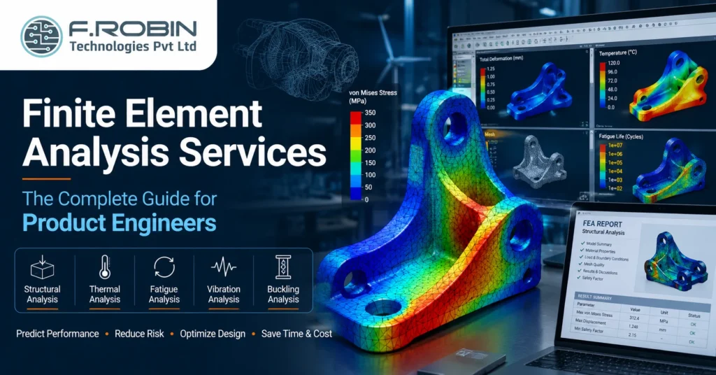
The solver outputs are visualized as color-coded contour plots (von Mises stress, temperature, displacement). Engineers interpret these results in the context of safety factors, material limits, and design codes (ASME, ISO, EN).
Step 7 — Design Recommendations
A professional FEA service doesn’t just hand you a stress map. The final deliverable includes an engineering report identifying failure risks, suggested design changes, and quantified safety margins.
Types of Finite Element Analysis
Not all FEA is the same. The type of simulation required depends on what could go wrong with your product. Here are the six most commonly used FEA types in mechanical engineering services.
1. Static Structural Analysis (Linear & Nonlinear)
The most widely used type. Static analysis applies loads that don’t change over time and checks for stress, strain, and deformation.
Linear static analysis assumes the material behaves elastically and deformations are small — suitable for most standard components under normal operating loads.
Nonlinear static analysis is required when dealing with large deformations, material plasticity (permanent yielding), or complex contact between parts. It is computationally heavier but necessary for realistic results in demanding conditions such as press-fit assemblies, rubber components, or highly loaded structures.
Typical use cases: structural brackets, frames, pressure vessels, machine parts, enclosure housings.
2. Thermal Analysis
Thermal FEA simulates heat transfer through conduction, convection, and radiation. It can be run as a standalone analysis or coupled with structural analysis (thermo-mechanical analysis) to evaluate thermal stresses.
- Steady-state thermal: heat distribution at equilibrium — useful for electronics cooling, heat exchangers, and engine components.
- Transient thermal: temperature changes over time — used for startup/shutdown cycles, welding simulations, and fire scenarios.
- Thermal stress analysis: calculates mechanical stresses generated by uneven temperature gradients and differential thermal expansion.
Typical use cases: PCB enclosure thermal management, heat exchangers, turbine components, engine blocks.
3. Dynamic and Vibration Analysis
Dynamic FEA evaluates how a structure responds to time-varying loads. The three primary subtypes are:
- Modal analysis: identifies the natural frequencies and mode shapes of a structure. Engineers use this to ensure operating frequencies don’t coincide with natural frequencies — which would cause resonance and potentially catastrophic failure.
- Harmonic analysis: examines the steady-state response to sinusoidal (periodic) loads, common in rotating machinery and vibrating equipment.
- Transient dynamic analysis: captures the full time-history response to sudden forces such as shock loads, impacts, and seismic events.
Typical use cases: rotating machinery, aerospace structures, automotive NVH (noise, vibration, harshness), industrial equipment.
4. Fatigue Analysis
Fatigue is responsible for the majority of mechanical failures in service. Fatigue FEA predicts how many load cycles a component can withstand before a crack initiates and propagates to fracture.
Two main methodologies are used: stress-life (S-N) for high-cycle fatigue in components that experience millions of load cycles, and strain-life (ε-N) for low-cycle fatigue where plastic deformation occurs each cycle.
Fatigue analysis is standard practice in automotive, aerospace, and rotating equipment design.
Typical use cases: suspension components, aircraft structures, pressure vessels under cyclic loading, pump impellers.
5. Buckling Analysis
Buckling analysis identifies the critical load at which a slender or thin-walled structure suddenly collapses under compressive forces — even before yielding occurs. The classic example is a column that bows and snaps under compressive load well below its material yield strength.
Typical use cases: aerospace panels, structural columns, thin-walled pressure vessels, offshore risers.
6. Computational Fluid Dynamics (CFD) — Coupled Analysis
While CFD is technically a separate discipline, it is frequently coupled with structural FEA in a workflow called Fluid-Structure Interaction (FSI). Pressure loads computed by CFD (airflow over a wing, fluid inside a pipe) are mapped onto an FEA model for structural validation.
Typical use cases: offshore pipelines, HVAC ductwork, turbine blades, heat exchanger tube bundles.
Industries That Use FEA Services
FEA services are used across virtually every engineering-intensive industry. Here are the sectors where simulation-driven design delivers the greatest return.
Aerospace and Defense
Every primary flight structure must be analytically justified before it flies. FEA is used to validate wing spars, fuselage frames, landing gear, and satellite structures against stringent certification requirements (FAA, EASA, MIL-STD). Solver dominance: NASTRAN with Femap/Patran pre/post-processing.
Automotive
Three FEA workstreams define automotive engineering: crashworthiness (explicit dynamics, LS-DYNA), NVH (noise, vibration, harshness), and fatigue durability. A single body-in-white model may be reused across all three with different load cases and solver settings.
Oil, Gas, and Process Industries
ASME Section VIII pressure vessel analysis, piping flexibility and stress analysis (Caesar II), skid package structural validation, and offshore structural assessments are standard FEA deliverables. Compliance with ASME, API, and EN standards is non-negotiable.
Electronics and Consumer Products
Thermal management of PCBs and enclosures, drop-test simulations for consumer devices, and structural analysis of plastics and sheet metal housings are high-demand FEA applications in this space. The intersection of mechanical and electronic design makes FEA especially valuable for electronics product companies.
Medical Devices
Implant stress analysis, fatigue life prediction for cyclic-loaded orthopedic implants, and housing structural validation for diagnostic equipment all require FEA. Regulatory submissions to FDA and CE often include FEA reports as supporting evidence of design safety.
Industrial Machinery and Manufacturing Equipment
Structural validation of frames, guarding, and fixtures; conveyor system fatigue analysis; press and stamping tool analysis. FEA reduces the number of physical test iterations on large, expensive hardware.
Benefits of Professional FEA Services
The business case for investing in FEA services is clear and quantifiable.
Reduced prototyping costs. Each physical prototype iteration for a mechanical product can cost ₹2 lakh to ₹20 lakh depending on complexity and material. FEA identifies design issues before metal is cut, eliminating multiple prototype rounds.
Faster time-to-market. Concurrent FEA simulation and design refinement is significantly faster than the build-test-fix cycle. Product development timelines can be reduced by 30–50% when simulation is integrated early.
Lower warranty and field failure risk. Products validated with FEA have demonstrably lower field failure rates. For liability-critical applications (medical devices, pressure vessels, structural components), FEA is not optional it is a regulatory requirement.
Design optimization. FEA doesn’t just check if a design will pass it tells engineers where material can be removed (lightweighting) and where geometry should be reinforced. This directly reduces manufacturing cost and improves performance.
Regulatory compliance evidence. Standards bodies like ASME, ISO, FDA, and CE increasingly accept or require computational analysis as part of design verification documentation. FEA reports serve as formal engineering evidence.
Access to specialized expertise without full-time headcount. Maintaining an in-house FEA team with licensed software (ANSYS licenses alone can cost $30,000–$80,000+ per seat per year) is expensive. Outsourcing FEA gives OEMs and engineering consultancies access to senior simulation expertise on a project basis.
FEA vs. Physical Prototyping: Which Should You Choose?
This is not an either/or question. FEA and physical testing are complementary — each has strengths the other lacks.
| Factor | FEA Simulation | Physical Prototype Testing |
|---|---|---|
| Cost per Iteration | Low (hours of engineering time) | High (materials, machining, test setup) |
| Time per Iteration | Hours to days | Days to weeks |
| Can Test Early Concepts | ✅ Yes, at CAD stage | ❌ No, requires physical geometry |
| Accounts for Real Material Variability | ❌ No (uses nominal properties) | ✅ Yes |
| Required for Regulatory Submission | Often yes (ASME, FDA support) | Often yes (physical test certificates) |
| Identifies Root Cause of Failure | ✅ Yes (full-field stress, strain, and deformation data) | ⚠️ Partially (typically limited to observable damage) |
| Validates Simulation Model | ❌ No | ✅ Yes — physical testing validates FEA predictions |
Top FEA Software Tools in 2026
The FEA software landscape is mature but evolving rapidly with AI-assisted meshing, cloud-based solvers, and generative design integration.
ANSYS Mechanical — the dominant commercial FEA platform globally. Comprehensive physics coverage (structural, thermal, fatigue, dynamics), strong CAD integration, and an increasingly AI-accelerated workflow with Ansys SimAI. The 2026 R1 release added direct electronics reliability analysis via Sherlock integration.
Abaqus (Dassault Systèmes) — the preferred platform for nonlinear analysis, rubber and elastomer simulation, and advanced contact problems. Widely used in automotive and aerospace for its solver robustness on difficult nonlinear problems.
NASTRAN (MSC/Siemens) — the industry standard in aerospace and defense, with decades of validation history and tight integration with MIL-STD certification workflows.
SolidWorks Simulation — accessible FEA integrated into the SolidWorks CAD environment. Ideal for product designers who need simulation results early in the design process without specialist FEA expertise.
Altair HyperWorks / OptiStruct — strong for optimization-driven design and lightweight structures. OptiStruct’s topology optimization capabilities are industry-leading.
SimScale — cloud-native FEA/CFD platform with a browser-based interface. Growing adoption among SMEs and startups for its lower barrier to entry.
Why Outsource FEA to India?
India has become one of the world’s leading destinations for engineering simulation outsourcing, and for good reason.
Cost advantage. FEA simulation work can be delivered at 40–60% of the cost of equivalent US or European teams, without compromising on technical quality. The cost differential is driven by engineering talent availability and lower operational costs not by cutting corners on software or methodology.
Depth of engineering talent. India produces over 1.5 million engineering graduates annually. The concentration of mechanical, aerospace, and electronics engineers many holding advanced degrees with FEA specialization is unmatched globally.
Established tool ecosystems. Indian engineering service providers routinely operate ANSYS, Abaqus, NASTRAN, and SolidWorks Simulation licenses and have extensive project portfolios across oil & gas, automotive, electronics, and aerospace sectors.
Time-zone advantage. For US and European clients, Indian FEA teams deliver overnight turnaround on simulation runs meaning design reviews can include updated FEA results from the previous evening’s solver run.
Standards compliance. Reputable Indian FEA providers work to ASME, ISO, EN, API, and client-specific standards. Design code compliance is a baseline expectation, not a premium service.
What to Look for in an FEA Service Provider
Choosing the right FEA partner is as important as the analysis itself. A poor simulation can give false confidence and lead to field failures. Here is what to evaluate.
Technical depth in your industry vertical. FEA in pressure vessels (ASME Section VIII) is fundamentally different from electronics thermal management or automotive crash simulation. Look for providers with documented project experience in your specific domain.
Software and hardware capability. Confirm the provider runs licensed commercial solvers, not cracked or student editions. Ask about their compute infrastructure large FEA models require high-RAM, multi-core workstations.
Report quality and engineering interpretation. A raw ANSYS stress plot is not a deliverable. Ask to see sample reports. Good FEA reports include: model description, load cases and boundary conditions, mesh quality metrics, result plots with scale and units, safety factor calculations, and actionable design recommendations.
Standards knowledge. If your product is governed by a design code (ASME VIII, EN 13445, AISC, API 650), the FEA team must demonstrate working knowledge of that code’s analysis methodology and acceptance criteria.
Revision and iteration support. FEA is iterative by nature. Confirm the provider’s process for handling design changes and re-runs within a project engagement.
Data security and NDA. Your CAD models and design data are proprietary. A serious FEA partner will sign a Non-Disclosure Agreement before reviewing any project files and maintain secure data handling protocols.
How F.Robin Technologies Delivers FEA Services
At F.Robin Technologies, our mechanical engineering team delivers end-to-end FEA simulation services from our engineering centres in Madurai and Bangalore. We serve clients across India, the US, Europe, and Southeast Asia.
Our FEA capabilities include:
- Static structural analysis (linear and nonlinear) — ANSYS Mechanical, SolidWorks Simulation
- Thermal and thermo-mechanical analysis — steady-state and transient, including electronics enclosure thermal management
- Dynamic and vibration analysis — modal, harmonic, transient dynamics
- Fatigue life prediction — stress-life and strain-life methodologies
- Buckling analysis — linear and nonlinear buckling
- Coupled FEA/CFD — fluid-structure interaction for pressure and thermal loads
We work to ASME, ISO, EN, and client-specified standards and deliver detailed engineering reports with safety factor summaries and design recommendations.
Our unique advantage: as a company that also delivers PCB design, PCB manufacturing, and electronics manufacturing services, we understand the specific challenges of electromechanical products — thermal management of electronics enclosures, structural analysis of PCB housings, and ruggedness validation for industrial electronics.
Ready to Validate Your Design with FEA?
Whether you’re optimizing a new product, investigating failures, reducing weight, or preparing for certification, our engineering team can help you leverage Finite Element Analysis (FEA) to improve performance, reduce risk, and accelerate product development.
